Modeling Framework
WavePiston Device
WavePiston is an novel wave energy converter comprising multiple energy collectors mounted along a submerged string, as shown in Figure 5. Each collector consists of a sail that captures surge motion from incoming waves and a hydraulic power take-off (PTO) that converts this motion into usable energy.
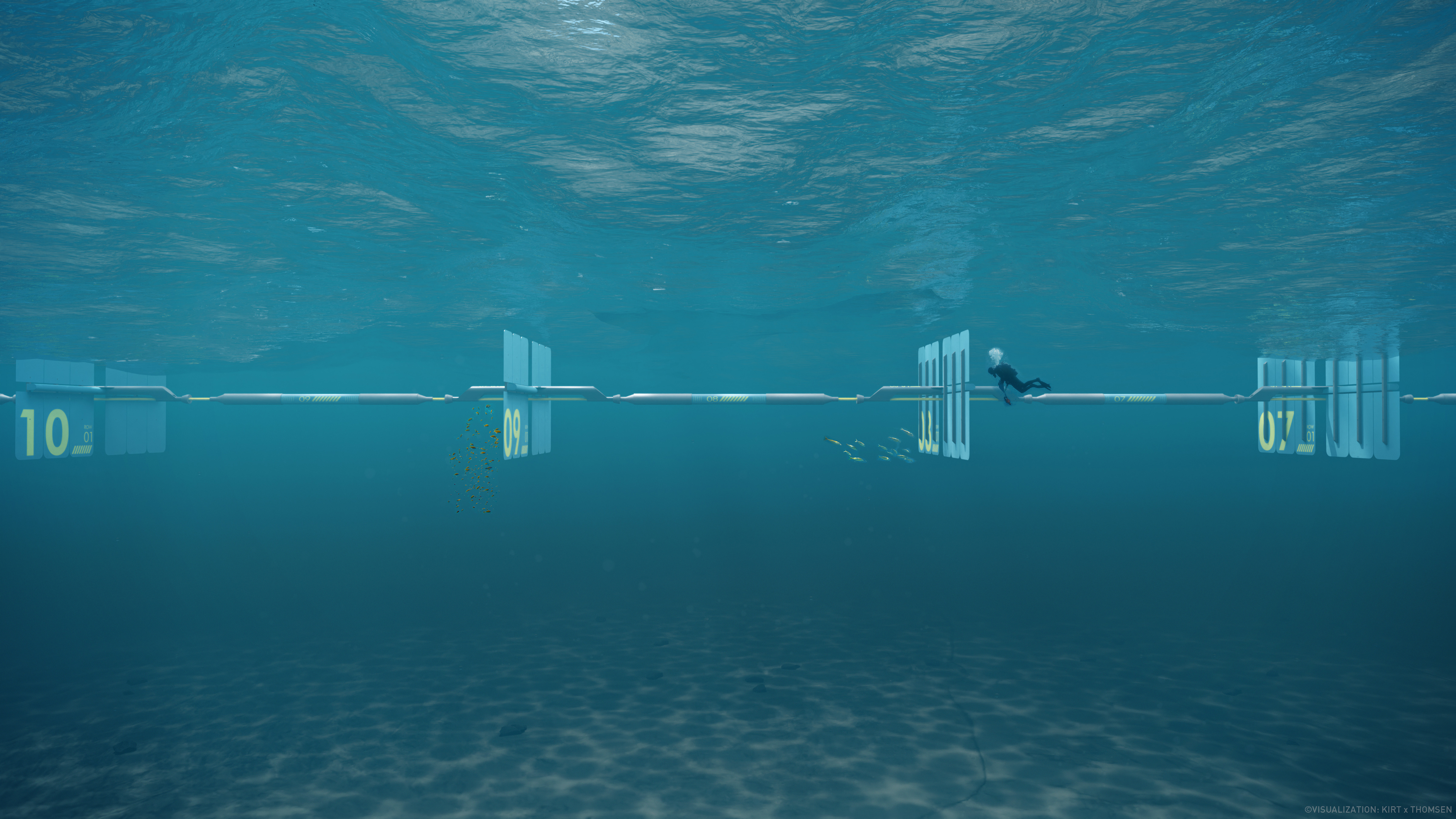
Figure 5 Illustration of the WavePiston WEC system, comprising a string of energy collectors. Image courtesy of WavePiston.
For the purpose of WAPPAC competition, a simplified one-sail, one-PTO configuration is used, schematically represented in Figure 6. This abstraction sufficiently captures the key dynamics of the WavePiston device within the competition scope.
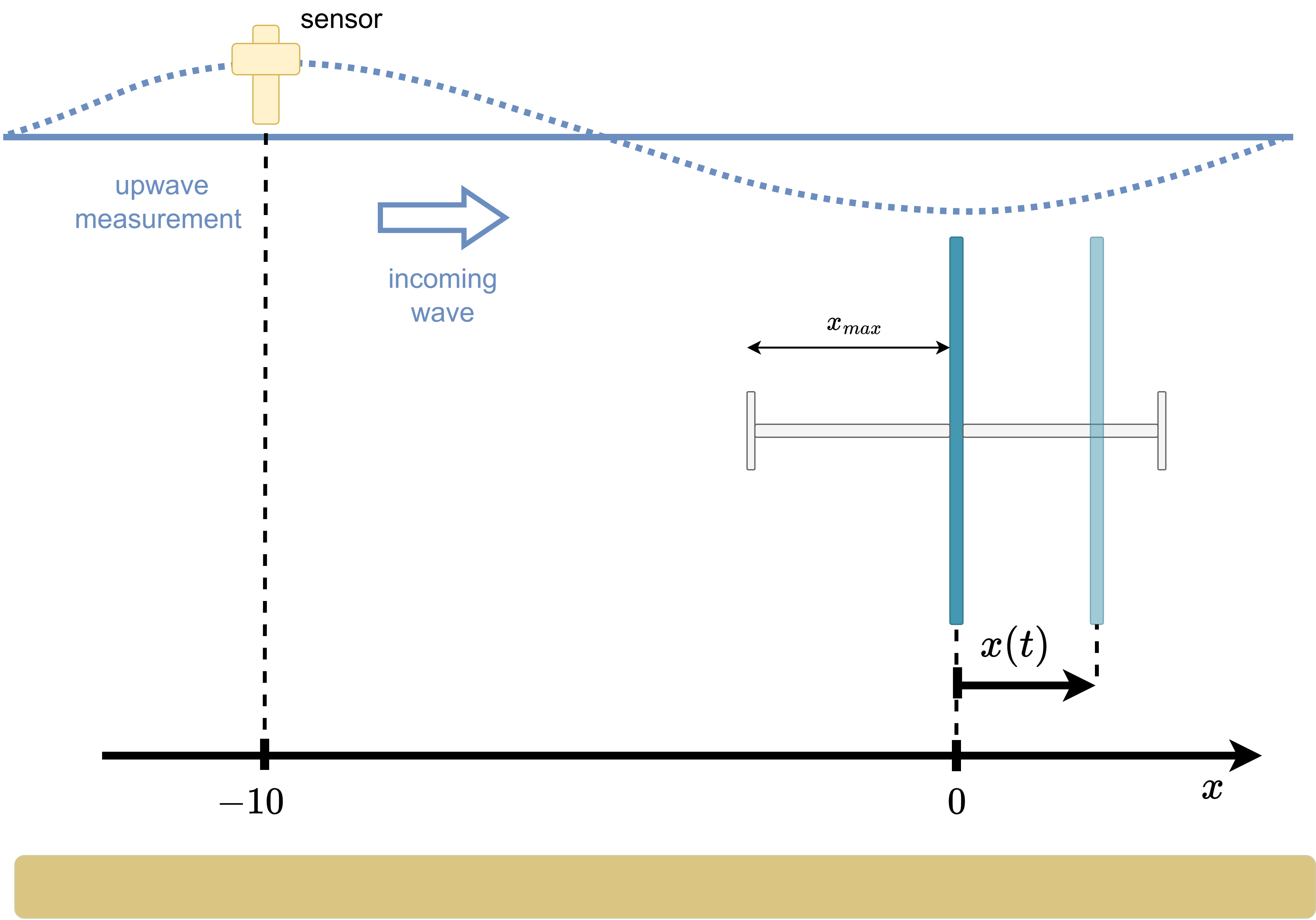
Figure 6 Schematic of the one-sail WavePiston device and up-wave surface elevation measurement.
WavePiston characteristics:
The device has one degree of freedom (DoF) along the surge direction.
The sail midpoint position is at \(x=0\), with incoming waves propagating along the positive \(x\)-axis (\(\beta=0\)).
The maximum allowable sail displacement is denoted by \(x_{\max}\).
Up-wave Measurement:
A sensor measures the up-wave surface elevation at \(x=-10\) m.
WavePiston Dynamics
The hydrodynamics of the simplified WavePiston device can be described using Cummins’ equation with an additional viscous drag term (1):
where:
\(x(t)\): sail position
\(\dot{x}(t)\): sail velocity
\(M = m_w + m_\infty\): total mass (device mass + added mass asymptote at infinite frequency)
\(F_{ex}(t)\): wave excitation force
\(F_{pto}(t)\): PTO control force
\(\rho\): seawater density
\(A_{sail}\): sail area
\(C_D\): viscous drag coefficient
The radiation force \(F_r(t)\) is approximated using a finite-order state-space model:
where \(\mathbf{\xi}(t)\) is the radiation state vector.
Note: No hydrodynamic restoring force acts on the WEC because the sails are constrained to move horizontally and are considered rigid. Therefore, this term is omitted from the hydrodynamic equation (1).
PTO Passivity Constraint
Due to the WavePiston design, the PTO can only extract power from the waves and cannot inject power back into the system. Consequently, the PTO power is constrained to be non-negative at all times:
This passivity constraint introduces a nonlinear constraint on the control strategies and is a critical factor in designing feasible, high-performance controllers for the competition.
Up-wave Measurement
Participants have access to the up-wave surface elevation measurement located at \(x=-10\) m, see the schematic representation in Figure 6. Linear wave theory is used for modeling the wave surface elevation. Please refer to Numerical Implementation for further details.